Passenger
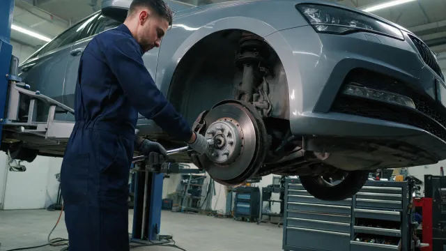
Match axle position and OE reference, then check ABS encoder and mounting geometry.
Applications
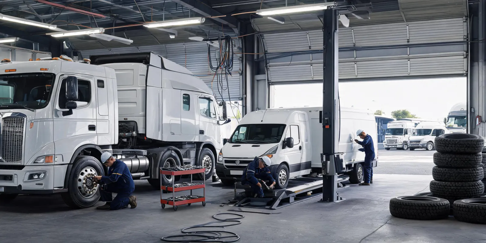
Different loads, surfaces and service schedules call for different questions.
Match axle position and OE reference, then check ABS encoder and mounting geometry.
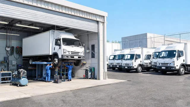
Plan replacement stock around vehicle mix, axle load and workshop schedules.
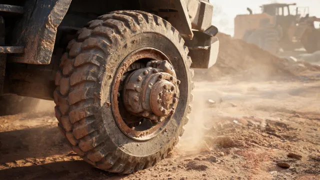
Review sealing and load cases in the context of dust, water and uneven terrain.
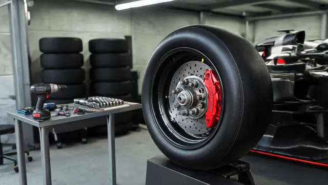
Define operating limits and testing needs for the specific application.

Consider seasonal duty, contamination and maintenance access.
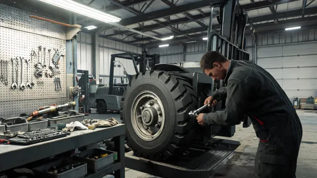
Document mounting dimensions and repeated low-speed loading.
Record axle loads, typical speed, mileage and planned workshop intervals. A fleet may need multiple part references even when vehicles look similar, so keep the platform and year with each line item. Separate front and rear positions when compiling the request.
Describe surface conditions, contamination, water exposure and load variation. These details help establish which seal, preload and inspection questions require attention. Record the duty cycle rather than relying on a broad vehicle category alone.
Do not assume that a visual match guarantees fit. Confirm the hub flange, bolt circle, bearing dimensions and wheel-speed sensor interface against the vehicle information. For wheel interfaces, PCD, offset and center bore are separate dimensions and should not be substituted for one another.
Where replacement history is available, retain the removed part reference and note any change to the vehicle or axle. Agree how installation and inspection will be carried out under the applicable service instructions. Product suitability and regulatory evidence should be reviewed for the destination market.
When comparing an integrated hub unit with a serviceable bearing arrangement, consider the actual vehicle design, the parts included in the repair and the workshop procedure. An integrated assembly may simplify some replacement operations, while a separate bearing can require a press and application-specific procedures. Tool availability and the vehicle design affect that choice. A selection should follow the platform requirements, not an assumption that either configuration is universally interchangeable.
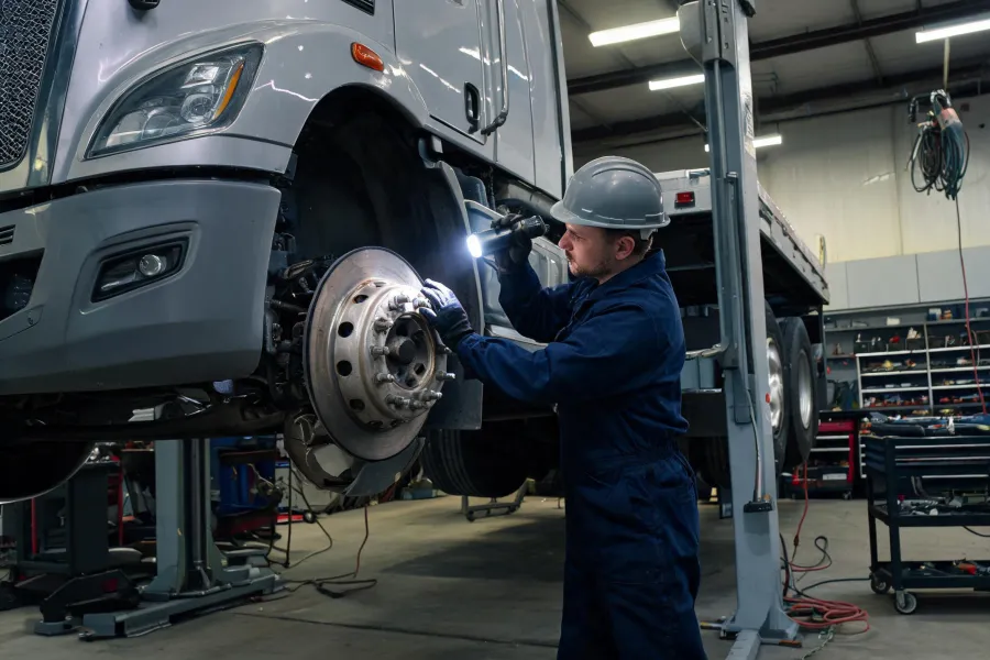
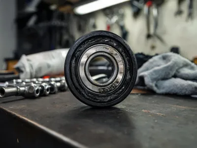
A photograph of the hub, sensor connector and mounting face can help clarify a request. Include measurements and the vehicle identifier; images alone do not establish compatibility.
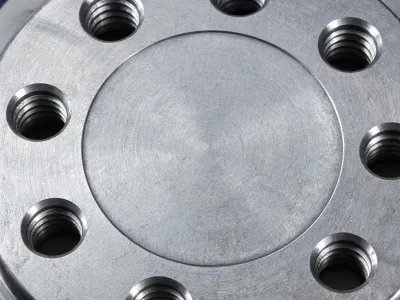

Bring your operating conditions and the part information you have.